Recently, I’ve started to embrace Fedora Silverblue (an immutable desktop OS) as my daily driver. One of the issues I encountered was trying to get my vscode (flatpak) to leverage remote containers via podman for development.
The following steps are fairly well documented to get started:
flatpak install com.visualstudio.code
flatpak install com.visualstudio.code.tool.podman
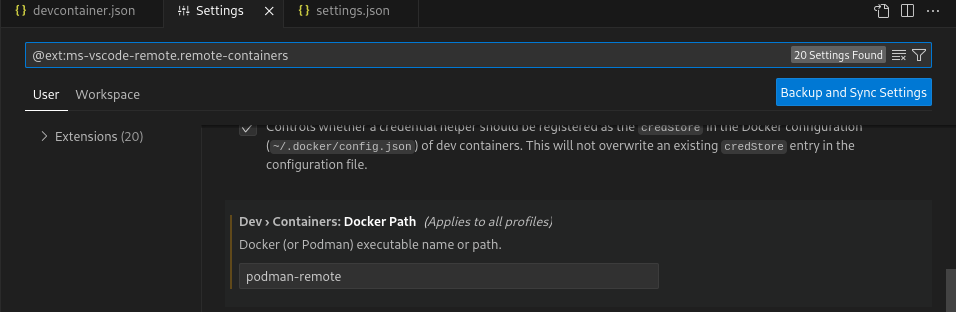
Set "dev.containers.dockerPath": "podman-remote" in VSCode settings/json:
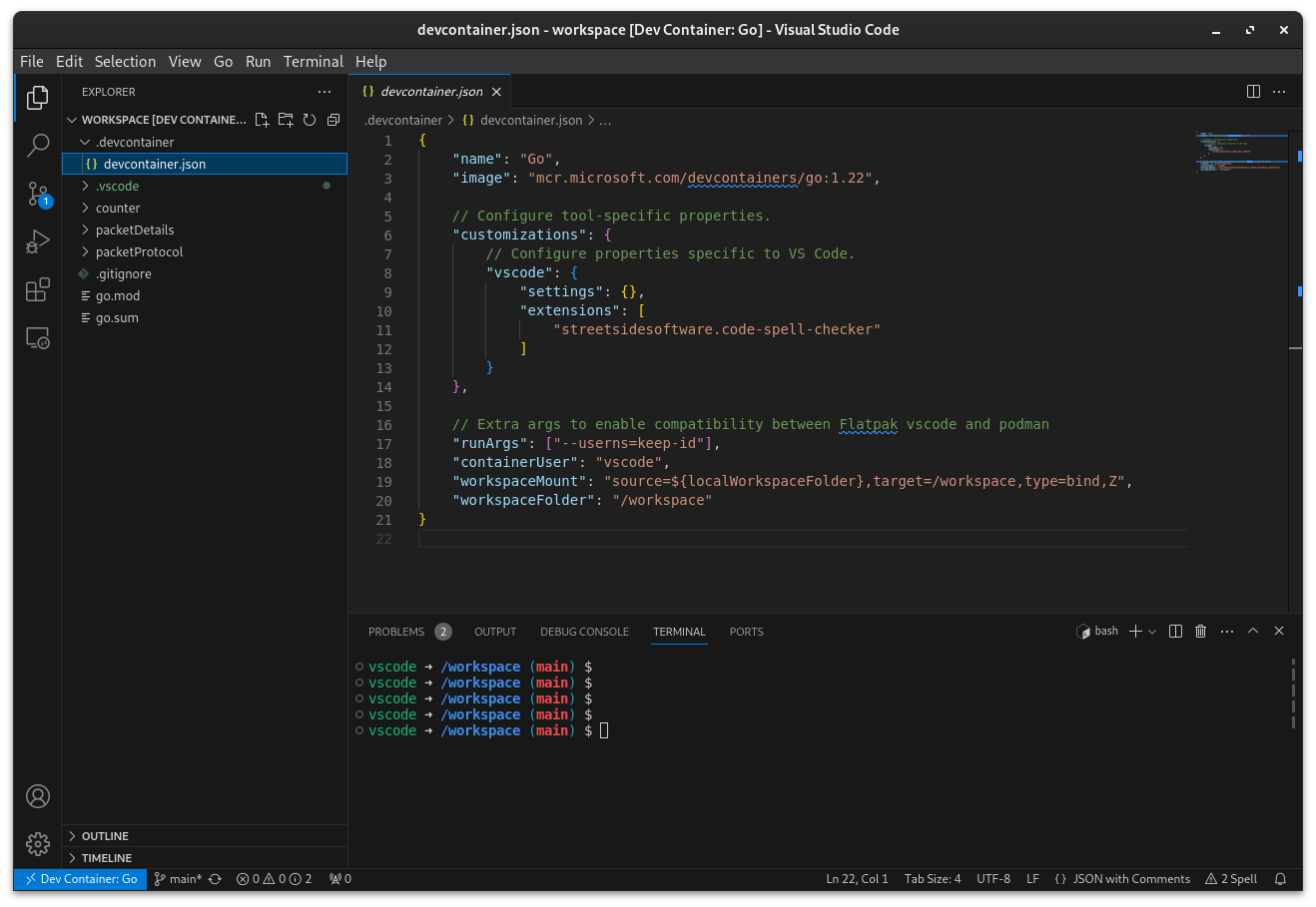
However, these following (mandatory) steps took a bit more digging around. In a repo’s .devcontainer.json file, add:
// Extra args to enable compatibility between Flatpak vscode and podman
"runArgs": ["--userns=keep-id"],
"containerUser": "vscode",
"workspaceMount": "source=${localWorkspaceFolder},target=/workspace,type=bind,Z",
"workspaceFolder": "/workspace"
Without doing so, I found my dev container attempting to mount the workspace incorrectly, resulting in a empty workspace view.
From my experience, some environments necessitate leveraging multiple NICs on Kubernetes worker nodes as well as the underlying Pods. Because of this, I wanted to create a test environment to experiment with this kind of setup. Although more common in bare metal environments, I’ll create a virtualised equivalent.
Planning
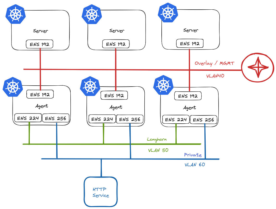
This is what I have in mind:
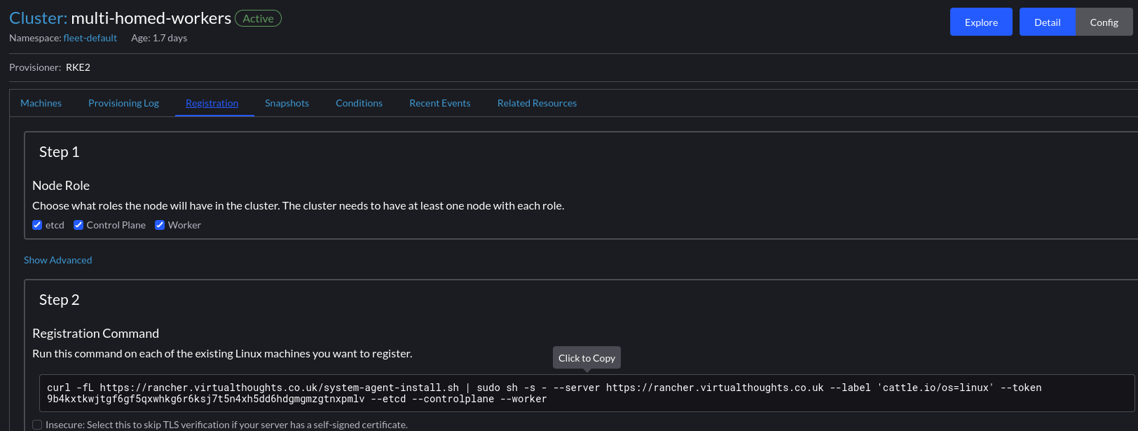
In RKE2 vernacular, we refer to nodes that assume etcd and/or control plane roles as servers, and worker nodes as agents.
Server Nodes
Server nodes will not run any workloads. Therefore, they only require 1 NIC. This will reside on VLAN40 in my environment and will act as the overlay/management network for my cluster and will be used for node <-> node communication.
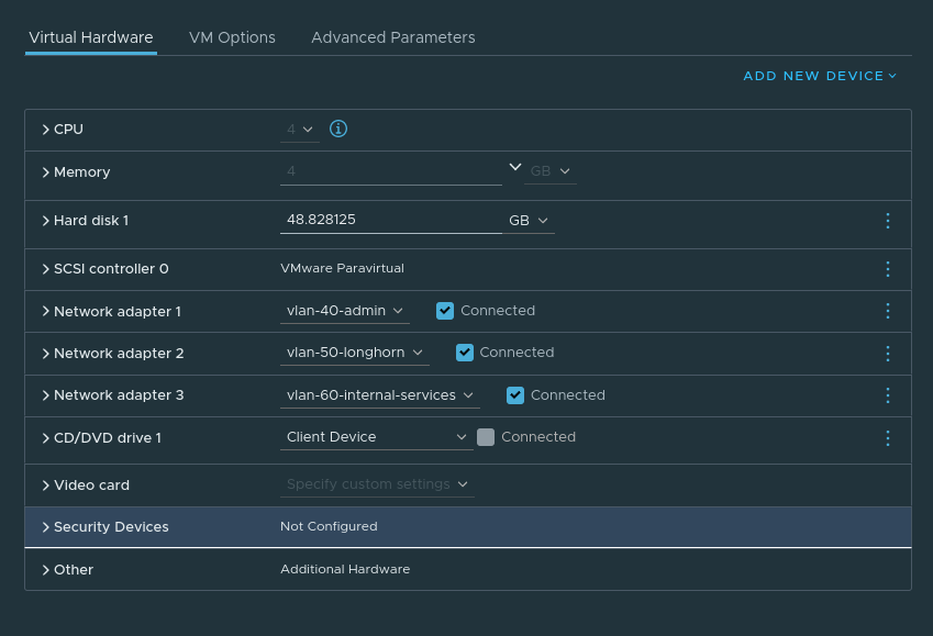
Agent Nodes
Agent nodes will be connected to multiple networks:
VLAN40 – Used for node <-> node communication.
VLAN50 – Used exclusively by Longhorn for replication traffic. Longhorn is a cloud-native distributed block storage solution for Kubernetes.
VLAN60 – Provide access to ancillary services.
Creating Nodes
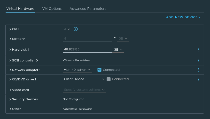
For the purposes of experimenting, I will create my VMs first.
Server VM config:
Agent VM Config:
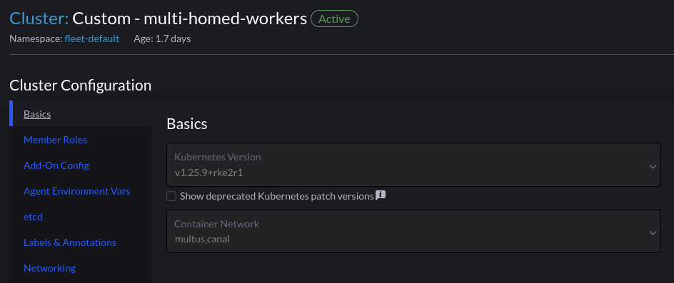
Rancher Cluster Configuration
Using Multus is as simple as selecting it from the dropdown list of CNI’s. We have to have an existing CNI for cluster networking, which is Canal in this example
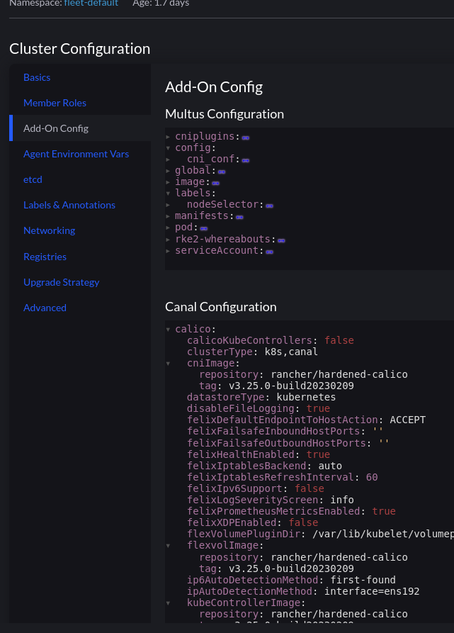
The section “Add-On Config” enables us to make changes to the various addons for our cluster:
Multus is not a CNI in itself, but a meta CNI plugin, enabling the use of multiple CNI’s in a Kubernetes cluster. At this point we have a functioning cluster with an overlay network in place for cluster communication, and every Pod will have a interface on that network. So which other CNI’s can we use?
Out of the box, we can query the /opt/cni/bin directory for available plugins. You can also add additional CNI’s if you wish.
For this environment, macvlan will be used. It provides MAC addresses directly to Pod interfaces which makes it simple to integrate with network services like DHCP.
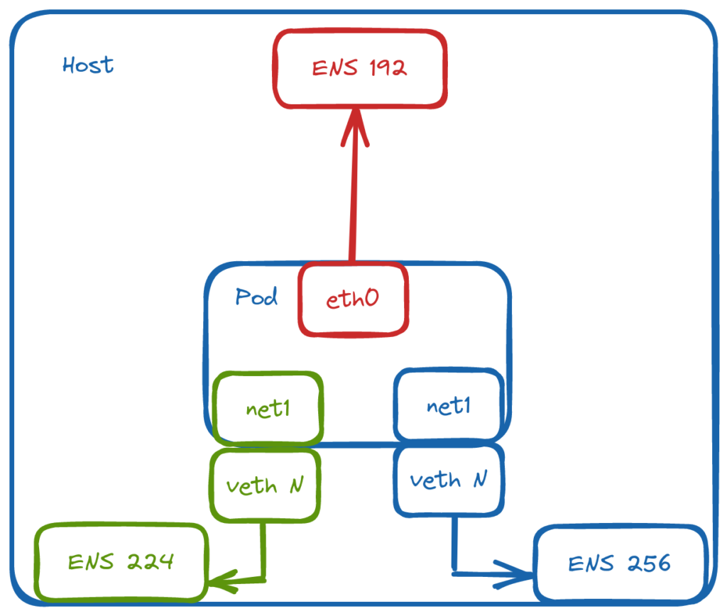
Defining the Networks
Through NetworkAttachmentDefinition objects, we can define the respective networks and bridge them to named, physical interfaces on the host:
root@net-tools:/# ip addr show
3: eth0@if2: <BROADCAST,MULTICAST,UP,LOWER_UP> mtu 1450 qdisc noqueue state UP group default
    link/ether 1a:57:1a:c1:bf:f3 brd ff:ff:ff:ff:ff:ff link-netnsid 0
    inet 10.42.5.27/32 scope global eth0
       valid_lft forever preferred_lft forever
    inet6 fe80::1857:1aff:fec1:bff3/64 scope link
       valid_lft forever preferred_lft forever
4: net1@if4: <BROADCAST,MULTICAST,UP,LOWER_UP> mtu 1500 qdisc noqueue state UP group default
    link/ether aa:70:ab:b6:7a:86 brd ff:ff:ff:ff:ff:ff link-netnsid 0
    inet 172.16.50.40/24 brd 172.16.50.255 scope global net1
       valid_lft forever preferred_lft forever
    inet6 fe80::a870:abff:feb6:7a86/64 scope link
       valid_lft forever preferred_lft forever
5: net2@if5: <BROADCAST,MULTICAST,UP,LOWER_UP> mtu 1500 qdisc noqueue state UP group default
    link/ether 62:a6:51:84:a9:30 brd ff:ff:ff:ff:ff:ff link-netnsid 0
    inet 172.16.60.30/24 brd 172.16.60.255 scope global net2
       valid_lft forever preferred_lft forever
    inet6 fe80::60a6:51ff:fe84:a930/64 scope link
       valid_lft forever preferred_lft forever
root@net-tools:/# ip route
default via 169.254.1.1 dev eth0
169.254.1.1 dev eth0 scope link
172.16.50.0/24 dev net1 proto kernel scope link src 172.16.50.40
172.16.60.0/24 dev net2 proto kernel scope link src 172.16.60.30
Testing access to a service on net2:
root@net-tools:/# curl 172.16.60.31
<!DOCTYPE html>
<html>
<head>
<title>Welcome to nginx!</title>
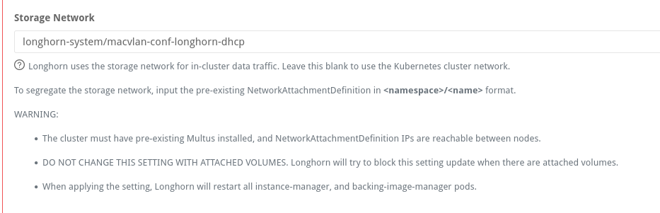
Configuring Longhorn
Longhorn has a config setting to define the network used for storage operations:
If setting this post-install, the instance-manager pods will restart and attach a new interface:
instance-manager-e-437ba600ca8a15720f049790071aac70:/ # ip addr show
1: lo: <LOOPBACK,UP,LOWER_UP> mtu 65536 qdisc noqueue state UNKNOWN group default qlen 1000
    link/loopback 00:00:00:00:00:00 brd 00:00:00:00:00:00
    inet 127.0.0.1/8 scope host lo
       valid_lft forever preferred_lft forever
    inet6 ::1/128 scope host
       valid_lft forever preferred_lft forever
3: eth0@if51: <BROADCAST,MULTICAST,UP,LOWER_UP> mtu 1450 qdisc noqueue state UP group default
    link/ether fe:da:f1:04:81:67 brd ff:ff:ff:ff:ff:ff link-netnsid 0
    inet 10.42.1.58/32 scope global eth0
       valid_lft forever preferred_lft forever
    inet6 fe80::fcda:f1ff:fe04:8167/64 scope link
       valid_lft forever preferred_lft forever
4: lhnet1@if4: <BROADCAST,MULTICAST,UP,LOWER_UP> mtu 1500 qdisc noqueue state UP group default
    link/ether 12:90:50:15:04:c7 brd ff:ff:ff:ff:ff:ff link-netnsid 0
    inet 172.16.50.34/24 brd 172.16.50.255 scope global lhnet1
       valid_lft forever preferred_lft forever
    inet6 fe80::1090:50ff:fe15:4c7/64 scope link
       valid_lft forever preferred_lft forever
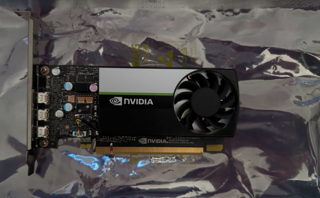
This post outlines the necessary steps to leverage the Nvidia GPU operator in a K3s cluster. In this example, using a gift from me to my homelab, a cheap Nvidia T400 GPU which is on the supported list for the operator.
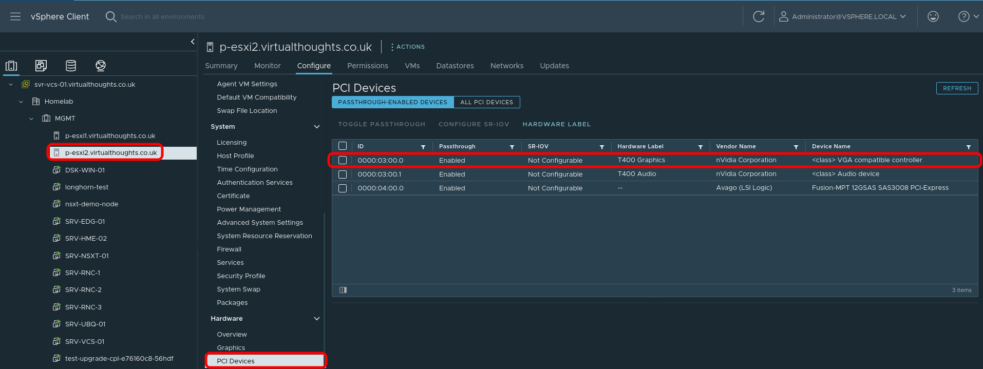
Step 1 – Configure Passthrough (If required)
For this environment, vSphere is used and therefore PCI Passthrough is required to present the GPU to the VM. The Nvidia GPU is represented as two devices – one for the video controller, and another for the audio controller – we only need the video controller. Steps after this are still relevant to bare metal deployments.
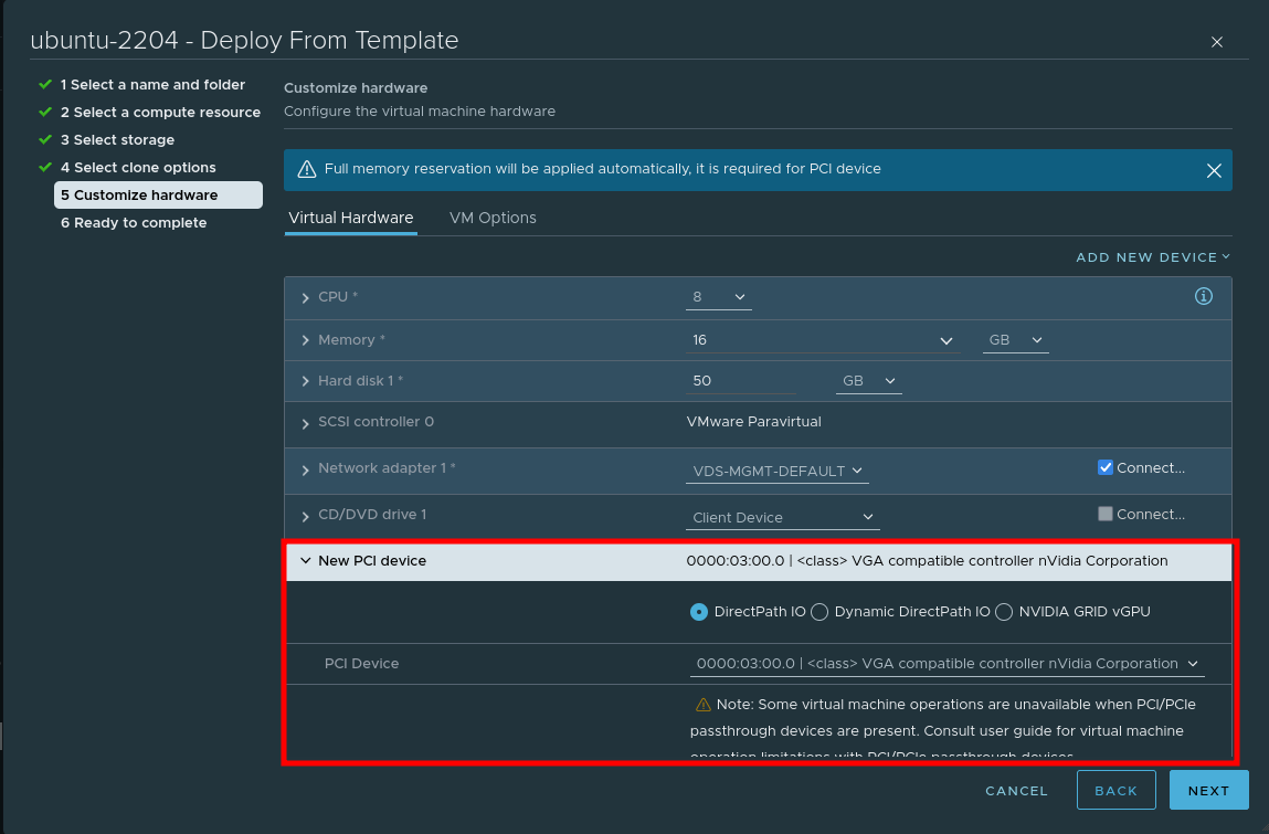
Step 2 – Create VM
When creating a VM, choose to add a PCI device, and specify the Nvidia GPU:
Step 3 – Install nvidia-container-runtime and K3s
In order for Containerd (within K3s) to pick up the Nvidia plugin when K3s starts, we need to install the corresponding container runtime:
Step 4 – Import Cluster into Rancher and install the nvidia-gpu-operator
Follow this guide to import an existing cluster in Rancher.
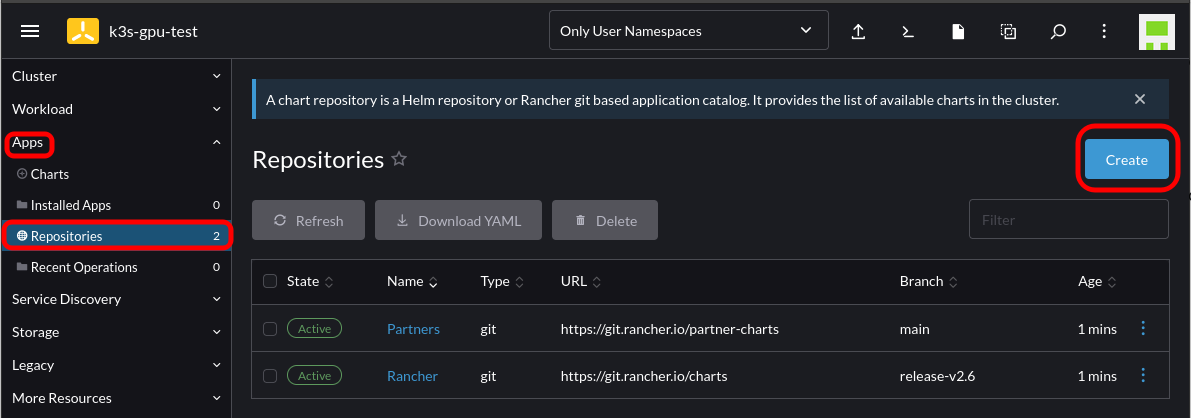
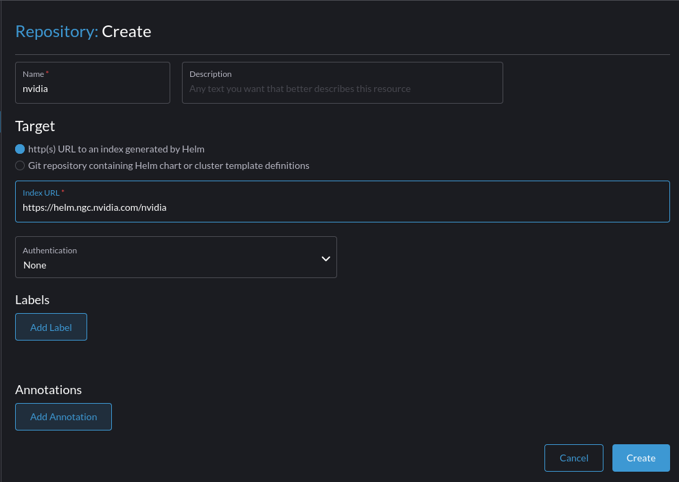
After which, Navigate to Rancher -> Cluster -> Apps -> Repositories -> Create
Add the Helm chart for the Nvidia GPU operator:
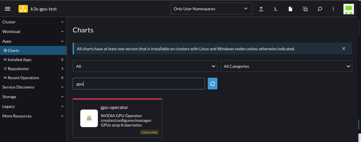
Select to install the GPU Operator chart by going to Cluster -> Apps -> Charts -> Search for "GPU":
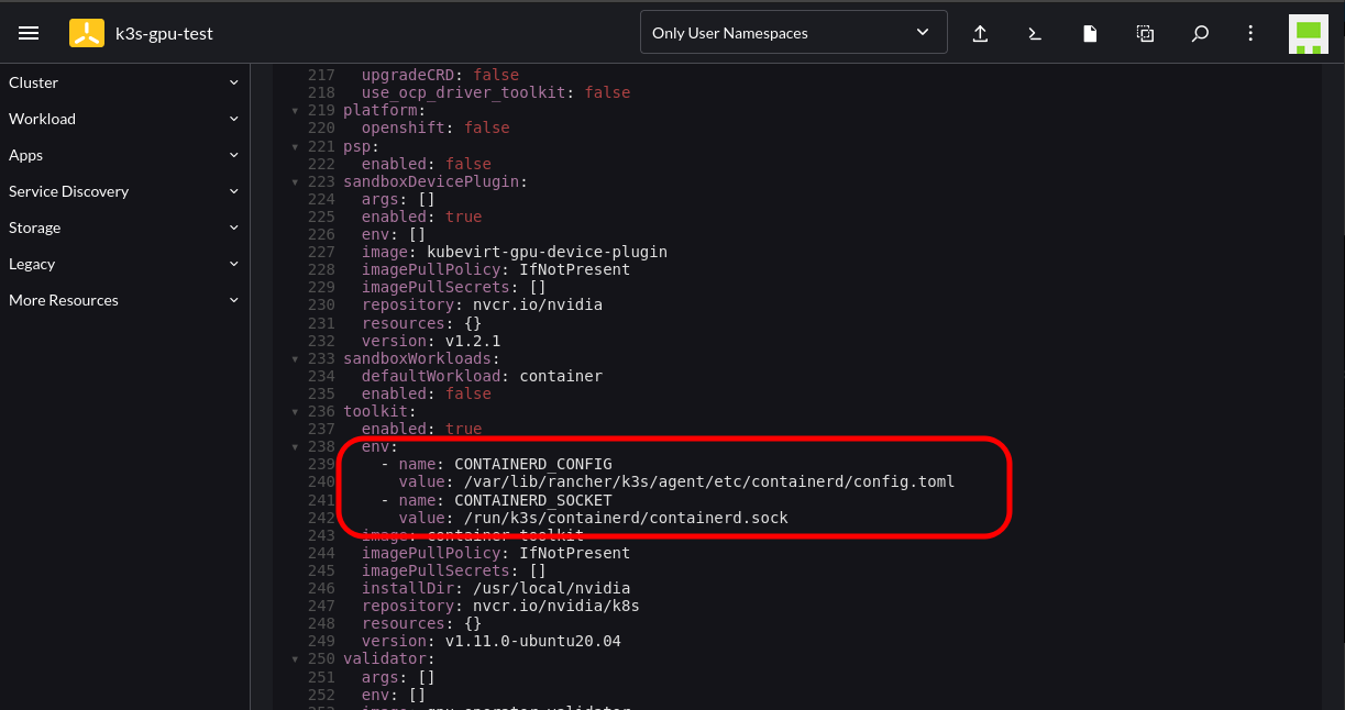
Follow the instructions until you reach the Edit YAML section. At this point add the following configuration into the corresponding section; this is to cater to where K3s stores the Containerd config and socket endpoint:
Proceed with the installation and wait for the corresponding Pods to spin up. This will take some time as it’s compiling the GPU/CUDA drivers on the fly.
Note: You will notice several GPU-Operator Pods initially in a crashloop state. This is expected until the nvidia-driver-daemonset Pod has finished building and installing the Nvidia drivers. You can follow the Pod logs to get more insight as to what’s occurring.
oot@ubuntu:~# kubectl logs nvidia-driver-daemonset-wmrxq
DRIVER_ARCH is x86_64
Creating directory NVIDIA-Linux-x86_64-515.65.01
Verifying archive integrity... OK
root@ubuntu:~# kubectl logs nvidia-driver-daemonset-wmrxq -f
DRIVER_ARCH is x86_64
Creating directory NVIDIA-Linux-x86_64-515.65.01
Verifying archive integrity... OK
Uncompressing NVIDIA Accelerated Graphics Driver for Linux-x86_64 515.65.01............................................................................................................................................
Logs from the Pod will indicate if it was successful:
root@ubuntu:~# kubectl logs cuda-vectoradd
[Vector addition of 50000 elements]
Copy input data from the host memory to the CUDA device
CUDA kernel launch with 196 blocks of 256 threads
Copy output data from the CUDA device to the host memory
Test PASSED
Without providing the runtimeClassName in the spec the Pod will error:
root@ubuntu:~# kubectl logs cuda-vectoradd
[Vector addition of 50000 elements]
Failed to allocate device vector A (error code CUDA driver version is insufficient for CUDA runtime version)!
Recent Comments